
In terms of its performance, the microstrip patch antennas can provide dual and circular polarizations and can be operated using two frequencies. Other features of this antenna include frequency agility, feedline flexibility, wide bandwidth, omnidirectional patterning and beam scanning. Another advantage of the microstrip patch antenna is the low cost involved and relative ease in manufacturing. Microstrip patch antennas gains an advantage over other microwave antennas in the area of portability as these antennas are lighter, and don't take much space. Together, with the increasing number of its users is the continuation of developing the method for more applications. In recent years, the use of microstrip patch antennas have increased because of the inherent advantages. The length and width of the microstrip patch antenna can be calculated using the formulas below. If the dielectric constant of the material is not known, you can choose to put in the velocity of propagation of the signal instead. This tool is designed to calculate the correct dimensions of a microstrip patch antenna if the operating frequency and the dielectric constant of the material used, is known. It uses 6mm aluminium tube for the radials, 4mm brass tube for the driven element and is built around an N-Type chassis socket mounted to a 40x40mm aluminium square, held together with rivets.A microstrip patch antenna is one of the most popular microwave antennas. The next two images show one I built for the 70cm band. I use one at home on 70MHz, click here to see construction details and more images. They are very forgiving due to the low impedance feed. I have made quite a few of these antennas over the years with good results. The radiating element is a quarter wave (/4) and the radials are 12 longer. (42° is the theoretical perfect angle for 50Ω feed, but who’s measuring!) This calculator can be used to design a Quarter Wave Ground Plane antenna, with radials. For VHF and below, as the elements get bigger, some more structured design is needed.Ī quarter wave monopole mounted against a perfect ground will have an impedance of around 36Ω but by bending the radials down at an angle of 45°, we increase this to around 50Ω whilst at the same time lowering the radiation angle more towards the horizon. These antennas can easily be built for UHF or above by using a chassis mount N-Type (or SO-239) connector, some solid wire and solder. You could cut a little on the large side and trim the antenna for best match at your desired frequency if you have the equipment. The velocity factor is set to 95% which should be fine for most people.

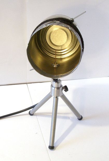
All pertinent considerations are included in the antenna factors including antenna gain and conversion to open circuit voltage. A cantenna can be used as a satellite dish feed horn. An antenna factor chart is supplied with each antenna. The Yagi Cantenna Dual-Band Wifi Extender is the worlds best.
This is a true unbalanced antenna, with a feed impedance of around 50Ω and therefore a great match to 50Ω unbalanced feedline. It is generally desirable to change to the horn feed above 5 GHz, but for less demanding applications the pyramidal log periodic feed can be used up to 10 GHz. There are usually four radials, three being a minimum, but you could use up to six. The radiating element is a quarter wave (λ/4) and the radials are 12% longer. In Europe it is possible to use the frequency range at 2.4 GHz and 5 GHz. Ahh, the good old quarter wave ground plane! This calculator can be used to design a Quarter Wave Ground Plane antenna, with radials. The antenna calculator supports you in this task and allows for corresponding.


 0 kommentar(er)
